Odometer and its simple applications
In this section, we will describe how to use the odometer. In this section, you will learn what the odometer means and how to get the odometer information.Laying the foundation for learning Navigation and Mapping. Also, the simple applications shown in this section will be applied toBehavior Tree.
1.What is an odometer
Odometer as described in the ROS Official Tutorial is abstracted by ROS as the following message structure:
Header header                                # ROS Message Header
string child_frame_id                        # Name of the chassis node in the ROS TF system
geometry_msgs/PoseWithCovariance pose        # Current position and pose information of the robot
geometry_msgs/TwistWithCovariance twist        # Robot current speed information
It describes the coordinates (x, y, z) of the robot in the world coordinate system with respect to the "origin" (which is not fixed and is user-defined) and the robot's pose information---Euler Angle(ROS transforms the Euler angle into Quaternion)。
2.How to get the odometer information of the robot
There are many methods to obtain odometer data, the common ones are kinematic methods and multi-sensor information fusion.
This tutorial will focus on kinematic methods. For reader who want to learn more, you can learn about visual odometry and algorithms related to inertial guidance on your own.
By processing the pulse data from the encoder mounted on the drive motor of the mobile robot chassis, we can obtain the accumulated number of degrees of rotation of the drive motor.
Then, we can calculate the current odometer data of the robot based on the mechanical specifications (e.g., robot wheel radius, distance between robot wheels, etc.) and the corresponding motion model of the robot (differential speed, omnidirectional, etc.).
(For more details, please refer toIntroduction to Autonomous Mobile Robots)
3.How to make the odometer more accurate
The careful reader may ask, "The parameters used in Section 2 are subject to mechanical (manufacturing and installation errors) and measurement errors, so is the odometer information obtained by kinematic methods accurate?
Indeed, the odometer information obtained by kinematic methods is not completely accurate, and even without mechanical and measurement errors, the application scenario of mobile robots is difficult to find perfectly horizontal ground, so the robot is bound to lose its orientation due to accumulated errors in the case of prolonged motion, making it impossible for the robot to move autonomously.
So how do we solve this problem and provide accurate positioning information for robot autonomy?
This involves the SLAM (simultaneous localization and mapping) problem, the general idea of which is to fuse information about the robot's environment with some of its own sensor data to obtain an optimal estimate of the robot's current localization information.
(This tutorial does not delve into the specific details of the SLAM algorithm, interested readers can refer to Slam For Dummies, Probabilistic Robotics and State Estimation For Robotics)
4. A simple application of odometer - Fixed Point Movement
To help the reader understand the odometer more rationally,this section will use a tutorial on ROS tf tree as an example to obtain the robot's positioning information in real time.And according to the current robot odometer information, to realize the robot's fixed-point movement and fixed-angle rotation.
Since the idea of fixed-point movement and fixed-angle rotation is roughly the same, this section will focus on how to implement fixed-point movement, all source files and demos are on our Github.
The program flowchart is shown below:
start=>start  : Set the target distance for forward/backward(t_dis),Set the moved distance (dis=0.0)
end=>end  : The target position has been reached and the robot stops moving.
move_robot=>operation  : Send the speed data
is_robot_arrived=>condition: t_dis-tol<=dis<=t_dis+tol?
start->move_robot
move_robot->is_robot_arrived
is_robot_arrived(no)->move_robot
is_robot_arrived(yes)->end
The demo launch process and results are shown below:
- 1 Open the
stagesimulation platform:
roslaunch handsfree_stage handsfree_simple_stage.launch
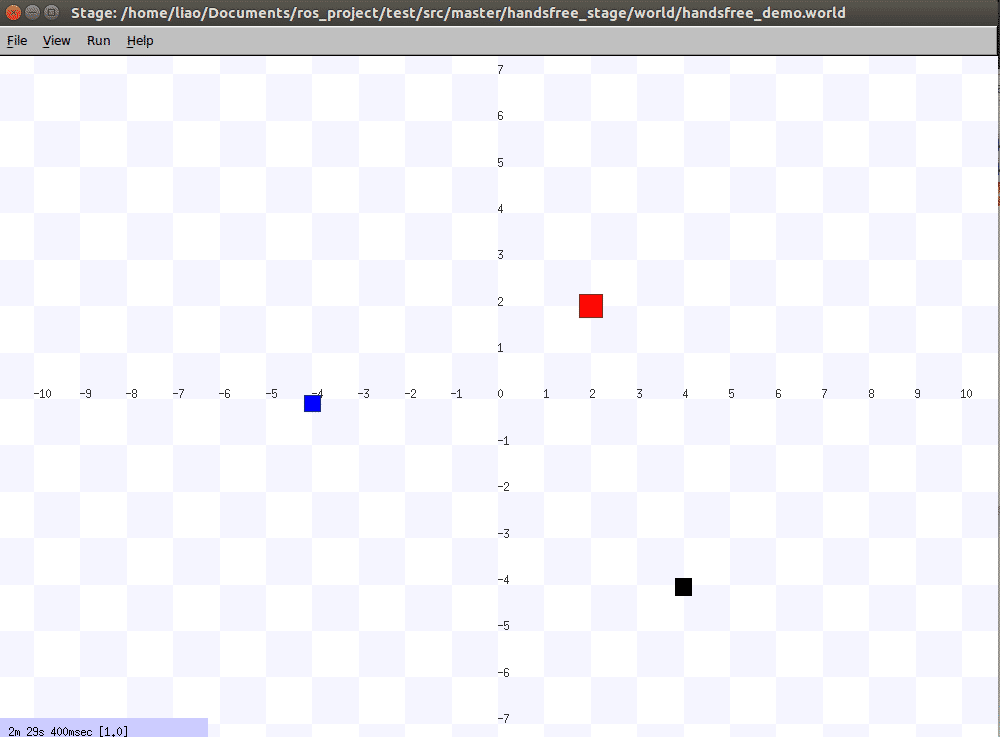
You can see the stage window on your desktop:
The small blue square in the figure is the robot, which is at the position (-4.0, -4.0) in the stage coordinate system, facing in the positive direction of the Y-axis.
- 2 Run the fixed-point movement program and assign a value to advance the robot 4.0 meters(Please make sure that the LinearMove.py program has been granted executable privileges first)
rosrun handsfree_smach LinearMove.py _t_dis:=4.0
Normally, the terminal displays the following information:

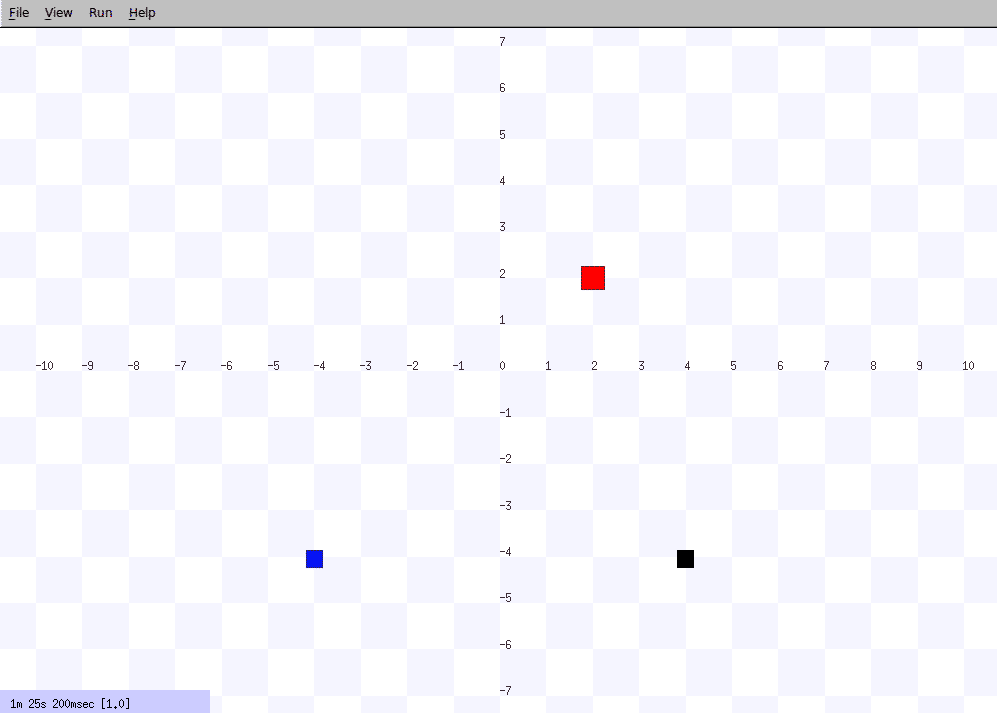
- 3 Observe the stage window, the small blue square in the stage is moving forward, and the robot reaches the target position after a period of time. At this point, the terminal output and stage status are shown below: