drive test
This section will introduce the test of the robot drive, in order to ensure that the various drives of the robot in your hand are not damaged during transportation. If you have any questions, please contact us in time.
Note: To close a terminal with a process running, use Ctrl+C in the window to interrupt the program, and then close the window.
1 Hardware Introduction
1.1 IMUs
IMU (English Inertial measurement unit, referred to as IMU) is an inertial measurement unit, which is a device for measuring the three-axis attitude angle and acceleration of an object. Generally, an IMU includes three single-axis accelerometers and three single-axis gyroscopes. The accelerometer detects the acceleration signals of the three-axis independent object in the carrier coordinate system, and the gyroscope detects the angular velocity signal of the carrier relative to the navigation coordinate system. Measure the angular velocity and acceleration of an object in three-dimensional space.
You can understand that the IMU can measure the attitude and position of the object. It plays an important role in the navigation of our robot.
1.2 Lidar
Lidar (referring to laser radar) laser radar is a radar system that emits laser beams to detect the position, speed and other characteristics of the target. Its working principle is to send a detection signal (laser beam) to the target, and then compare the received signal (target echo) reflected from the target with the transmitted signal, and after proper processing, the relevant information of the target can be obtained, such as Target distance, azimuth, height, speed, attitude, and even shape parameters, so as to detect, track and identify some objects.
Lidar plays an important role in our robot mapping and navigation.
1.3 rgbd_camera
rgbd_camera (RGB-D camera, also called depth camera) = ordinary RGB three-channel color image + depth image
In 3D computer graphics, a Depth Map is an image or image channel that contains information about distances to surfaces from viewpoint scene objects. Among them, the Depth Map is similar to a grayscale image, except that each pixel value of it is the actual distance from the sensor to the object. Usually the RGB image and the Depth image are registered, so there is a one-to-one correspondence between pixels.
1.4 Gimbal
The pan/tilt is a supporting device for installing and fixing the camera, and it is divided into two types: fixed and electric pan/tilt. giraffe and stone are motorized gimbals, so we need to test them.
2 Robot hardware connection test
Before the official test, let's check the connection of various devices. Here we take HandsFree Gemini and omni robot as examples, open the terminal and run in sequence:
- lsusb
- ls /dev/HFRobot
- ls /dev/lidar_front
The terminal displays the following:
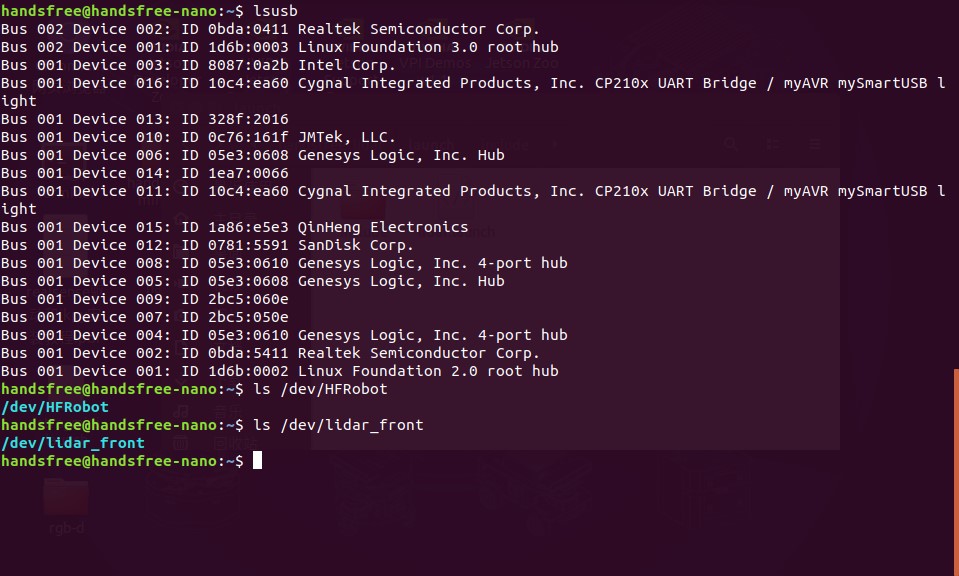
Found two CP210x UART BridgeUSB devices, one of which is a front lidar, and mapped to /dev/lidar_front at the OS layer. The other one is the chassis motion control board and is mapped to /dev/HFRobot at the operating system level. The IMU sensor is already included on the chassis motion control board.
If there is a problem with the above tests, please check whether the connection between the robot and each device is normal, and whether the HandsFree software environment of the host is configured completely. Then perform subsequent tests.
If running the ls /dev/lidar_front command still does not respond
- Please enter the
/etc/udev/handsfree-serial.rulesfile to check whether the corresponding value of SYMLINK after the UART Bridge Controller item is "lidar_font" - If not, enter the directory
~/handsfree/handsfree_ros_ws/src/handsfree/Documentation, enterbash set_usb_env.shin the terminal to execute the usb rule file, and then check the SYMLINK in step 1 Corresponding value, if "lidar_front" is displayed normally, thels /dev/lidar_frontcommand can be executed correctly
3 IMU test
Tips: Please do not shake the robot before powering on, otherwise, when performing IMU testing, the visual interface will show that the model is not level or is constantly rotating.
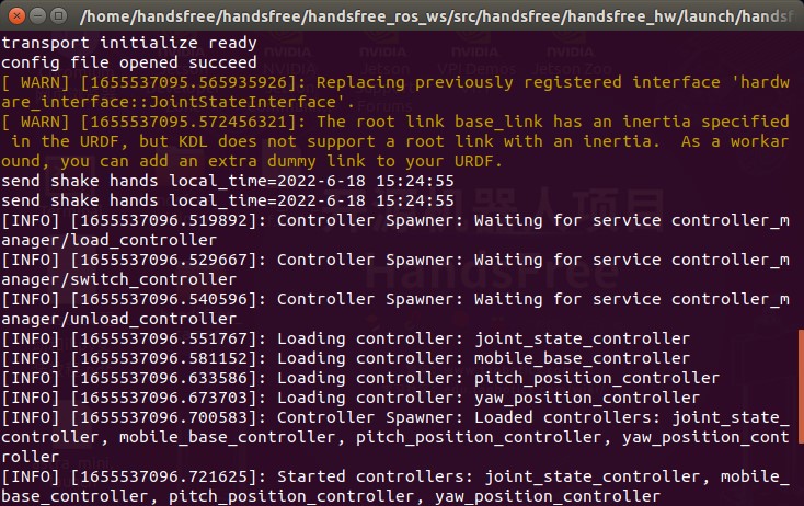
Open the terminal (Ctrl+Alt+T), enter the following command to start our robot
roslaunch handsfree_hw handsfree_hw.launchNormally, it will display:
Open the second terminal (Ctrl+Alt+T or Ctrl+Shift+T), enter the following command to open the rviz visual interface
roslaunch handsfree_hw view_rviz.launchUnder normal circumstances, it will display: (If the image below does not appear, you can check all the options as shown)
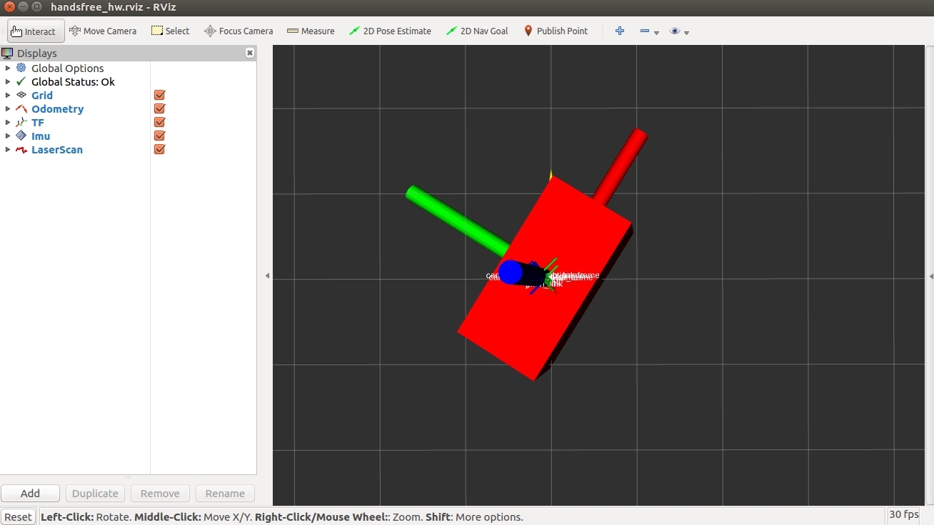
Now if you shake your robot, you can see that the model of the visual interface will also shake.
Test the robot's IMU Turn the robot, try to rotate it 180 degrees first, check whether the model has rotated 180 degrees through the visual interface, and then turn it 180 degrees to let the robot rotate a circle and return to its original position. At this time, check whether the model in the visual interface has returned to its original position, and it has also rotated in a circle. If you actually rotated 180 degrees, and the model of the visual interface rotated 360 degrees, then there is a problem with this IMU.
tips1: Press and drag the left mouse button to rotate the view, press the left mouse button + Shift and drag to move the view up, down, left, and right.
tips2: If the screen shows that the gyroscope is not level or is constantly rotating, it may be that the robot was shaken when the power was first turned on. Please close all programs, power off the robot, and then power on again. Do not shake the robot during power-on.
4 Lidar test
HandsFree supports a variety of lidars, such as Silan's rplidar A1/A2/A3, Hokuyo series radars, etc.
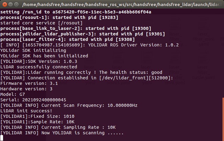
Open a new terminal, enter the following command to open the laser node
roslaunch handsfree_lidar lidar.launchNormally, it will display
Open a new terminal and check whether the radar is normal through the visual interface
roslaunch handsfree_hw view_rviz.launch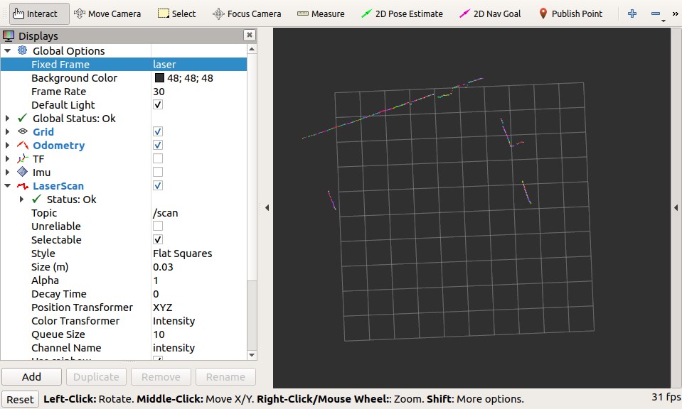
After opening the interface, you can compare the visual interface with the real environment where the robot is currently located. The colored lines that appear on the screen correspond to obstacles in the real environment.
You can place obstacles around the robot to observe how quickly the information on the visual interface changes to check the real-time performance of the radar. If the visual interface changes after 10 seconds, then there is something wrong with the robot radar.
5 rgbd_camera test
HandsFree supports a variety of depth cameras, including Xtion Pro, Obi Zhongguang, Kinect, etc. Please start the camera driver according to the actual camera model. This tutorial uses gemini as an example to start the Dabai camera
We have a depth camera device in our package, all of which are connected to USB 3.0, open the terminal, and run the following command
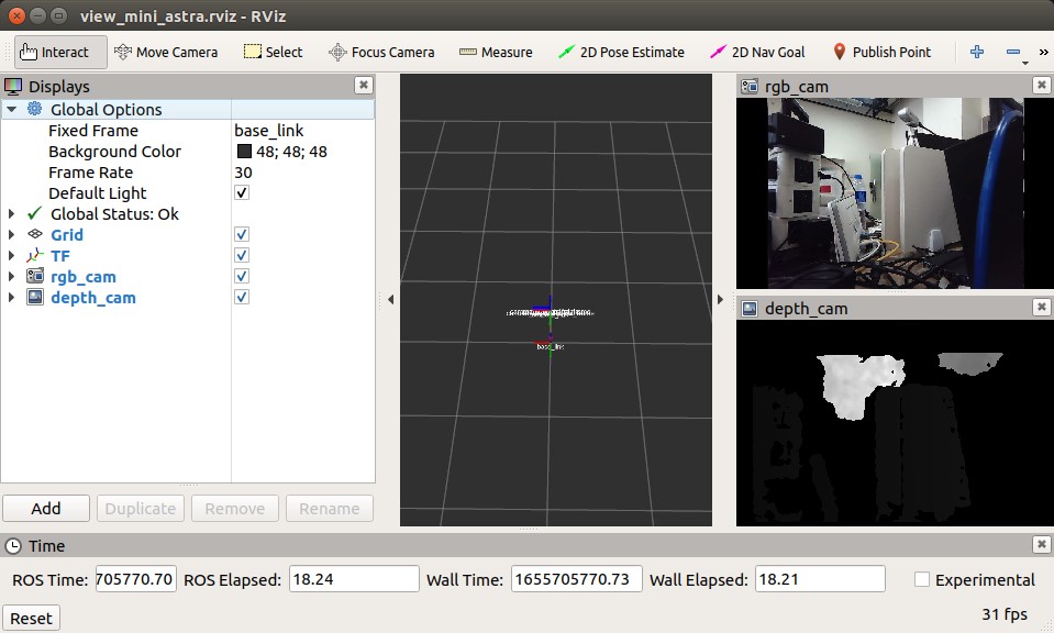
roslaunch handsfree_camera view_camera.launchThe rviz visualization interface will open, and two Image boxes will appear. The upper window will display the RGB image, and the lower window will display the depth image.
You can shake your palm in front of the camera to check the changes in the image in the Image frame to check whether the camera is working properly.
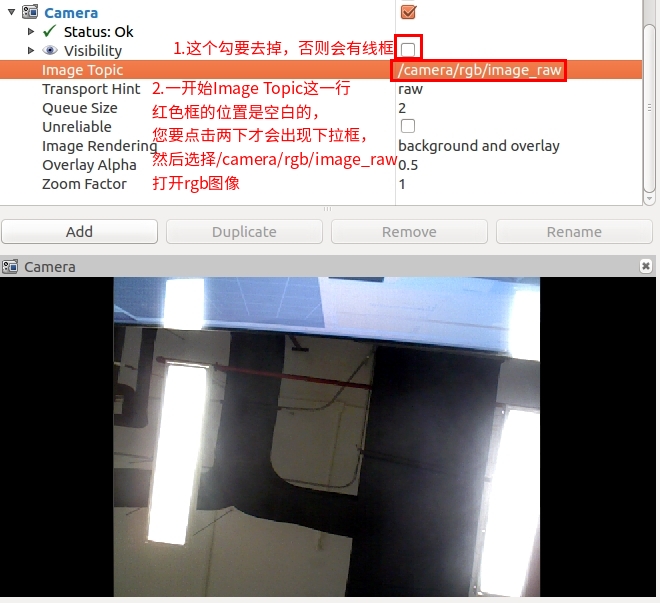
If your rviz visual interface does not have those two camera windows, you need to add them manually, click the
Addbutton in the lower left corner to add, a small window will pop up, selectImageinside, and then clickokIt will be added successfully.After the addition is successful, you need to make settings to make the Image box display the image. Find the Image in the sidebar and click to expand it. Uncheck the Visiblity check box and set the image topic of the Image Topic. Generally, we choose /camera/ rgb/image_raw or /camera/depth/image_raw
6 PTZ test
This function is only available for some products
Open the terminal (Ctrl+Alt+T), enter the following command to start our robot (if it has been opened before, please ignore this step)
roslaunch handsfree_hw handsfree_hw.launchOpen the second terminal, and enter the following commands one by one to let the gimbal complete some actions
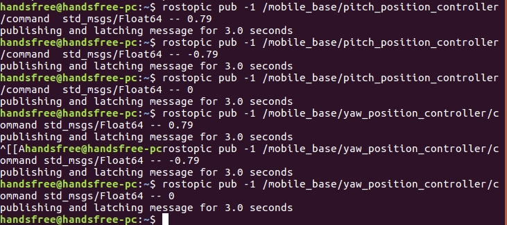
Gimbal looking up at 45 degrees:
rostopic pub -1 /mobile_base/pitch_position_controller/command std_msgs/Float64 -- 0.79Gimbal overlooking 45 degrees:
rostopic pub -1 /mobile_base/pitch_position_controller/command std_msgs/Float64 -- -0.79Gimbal pitch centered:
rostopic pub -1 /mobile_base/pitch_position_controller/command std_msgs/Float64 -- 0Gimbal turn left 45 degrees:
rostopic pub -1 /mobile_base/yaw_position_controller/command std_msgs/Float64 -- 0.79Gimbal turn right 45 degrees:
rostopic pub -1 /mobile_base/yaw_position_controller/command std_msgs/Float64 -- -0.79Gimbal yaw centered:
rostopic pub -1 /mobile_base/yaw_position_controller/command std_msgs/Float64 -- 0Under normal circumstances, the gimbal will complete the rotation at all angles.
7 Chassis drive test
Run the program and test the robot's ability to move remotely through the keyboard. For this part, you can refer to the tutorial [Remote Control Robot] (docs/handsfree/handsfree-en/Tutorial/Beginner/1.2-Remote-Your-Robot /doc.html)