Thunder User Manual
1 Introduction
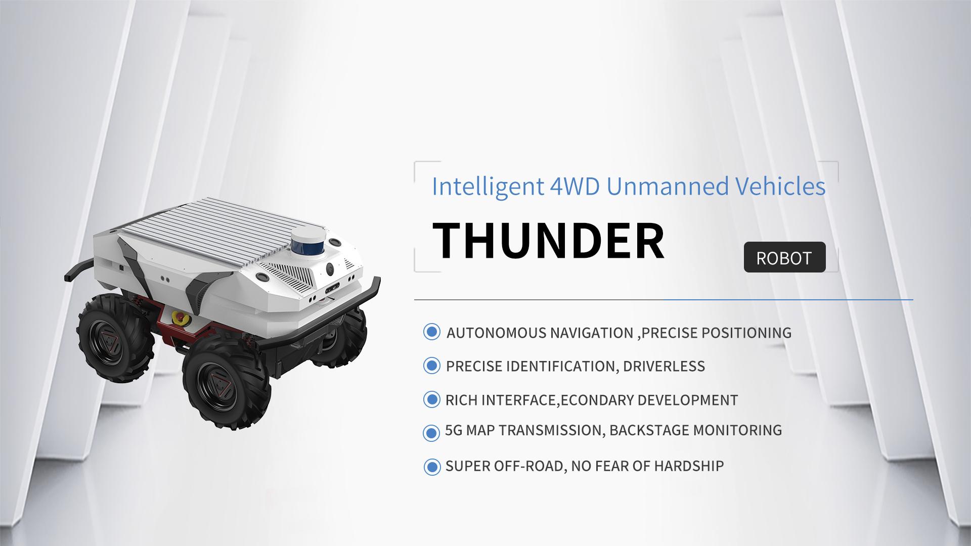
HandsFree Thunder is a high-performance ummanned robot developement platform with four-wheel differential drive chassis layout.Utilize a multi-function controler OpenRE Board which based on the 32-bit STM32F407 chip, making it possible to drive various on-board resources and secondary development interface, including ten-axis intertial test unit, ultrasonic sensor, odometer etc.
Thunder occupies Power Manager power control system. Except for providing battery charge and discharge protection, overcurrent protection and power display, it can also provide stable power source output, including 5V, 12V, 19V, 24V, making it convience to drive the upper equipments. As usual, Thunder inherites the symbols of high-versatility and high-expandability. Thunder also supports multi mainstream LiDAR, computing platform and camera, including Silan, Beiyang, industrial control machine, TK1, TK1/2, Xtion1/2, Kinetic 1/2, ZED Stereo Camera. In addition, the rugged, high-stable structure making it equal to motivate Handsfree large robotarms, UR3/5 robotarms and Kinova robotarms, which makes it qualified for multi missions.
Thunder occupies hardware odometer, inertial test units, LiDAR , stereo vision camera and voice array etc, which adapts to ROS TF, Navigation, Actionlib and Pluginlib subsystems perfectly, making it a good platform to learn ROS and verify high-level robot algorithms. In addition, with complete development tutorials and after-sales service technology, Thunder supports both OpenRE and ROS system, making it qualified for ROS developmeny, SLAM study, machine learning, as well as the study and development of commercial robots.
2 Package Contents
The list of Thunder high-end shipments is as follows, the following list is for reference only
| No. | Name | Image | Quantity |
|---|---|---|---|
| 1 | Thunder Robot | 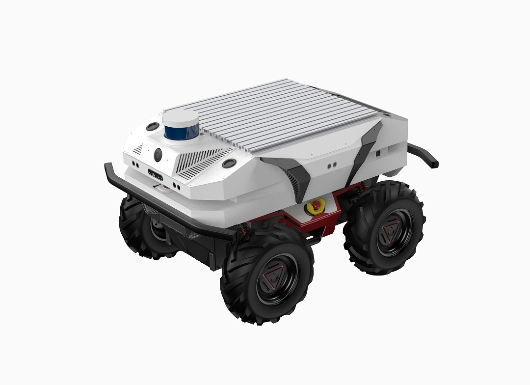 |
x1 |
| 2 | Battery Charger(AC 220V) | 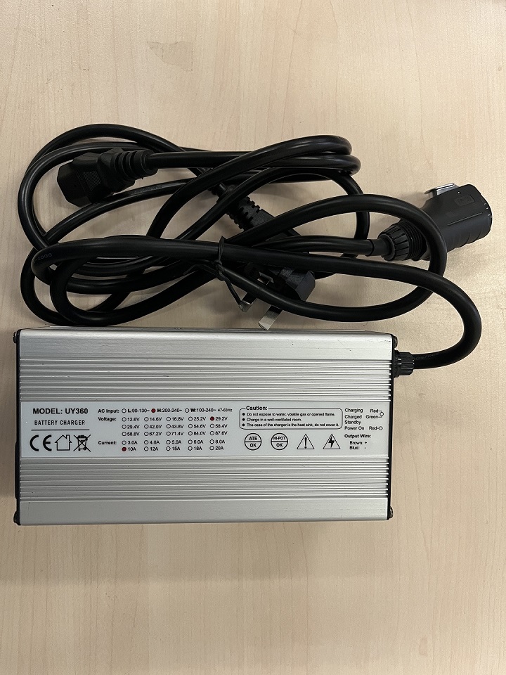 |
x1 |
| 3 | FS Transmitter | 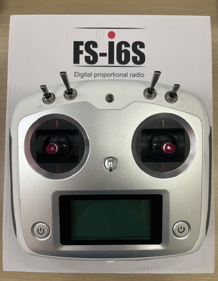 |
x1 |
| 4 | Mouse&keyboard | 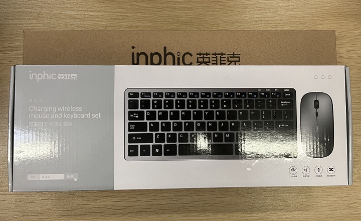 |
x1 |
| 5 | Toolkits |  |
x1 |
| 6 | User manual |  |
x1 |
| 7 | Product Warranty Certificate/After-Sale Service Manual |  |
x1 |
| 8 | Inspection Sheet |  |
x1 |
| 9 | Product certificate |  |
x1 |
3 Product Overview
3.1 The Basic
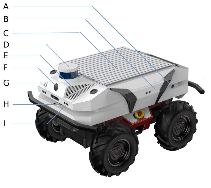
| No. | Description |
|---|---|
| A | Main Power Switch |
| B | Aluminum Expansion Board |
| C | Built-in 4/5G networking module |
| D | 3D Lidar |
| E | Hi-Fi |
| F | Camera |
| G | RGBD Camera |
| H | 2D Lidar |
| I | Multiple Ultrasounds |
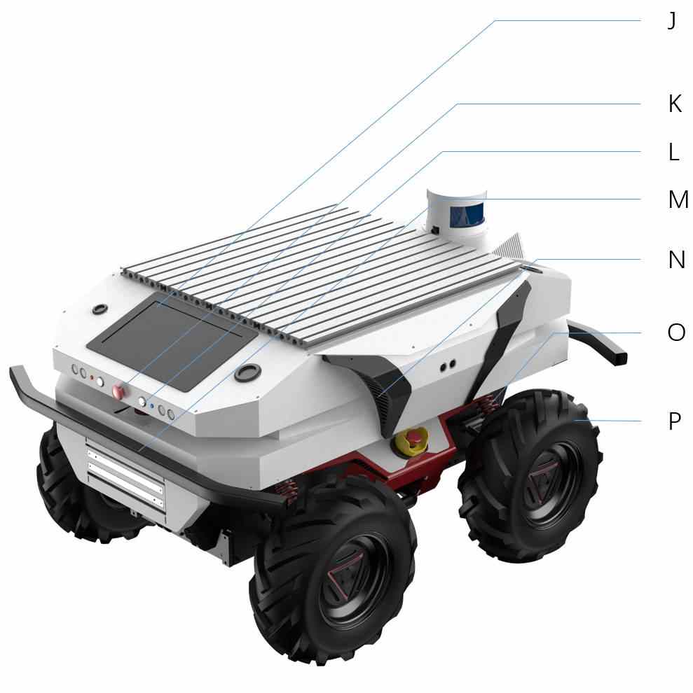
| No. | Description |
|---|---|
| J | 10-inch IPS display |
| K | Emergency Stop Switch |
| L | Reserved Function Button |
| M | Crash Sensor |
| N | Circulating cooling system |
| O | Independent Suspension Shock Absorption System |
| P | All Terrain Off-Road Tires |
3.2 Rear Electrical Interface

- Q1 is the charging interface;
- Q2 is the extension interface for CAN and 24V power supply;
- Q3 is the Buzzer;
- Q4 is the main switch;
- Q5 is the power display interaction。
3.3 State instruction
Users can identify the status of robot through the voltmeter, the buzzer and lights mounted on Thunder.
| State | Description |
|---|---|
| Current voltage | The current battery voltage can be viewed via the voltmeter in the tail electrical panel, accurate to 1V |
| Low voltage alarm | When the battery power is below 15% or the voltage is below 24V, the robot will give a "beep-beep-beep" sound as warning. When the battery level is below 10% or the voltage is below 23V, Thunder will actively cut off the external extension power supply and drive power supply to prevent the battery from being damaged, and the chassis will not be able to control the movement and receive external commands. |
| Power-up display | Front and rear lights are switched on. |
3.4 Description of the Rear Electrical Interfaces

| Pin No. | Pin Type | Function&Definition | Note |
|---|---|---|---|
| 1 | Power supply | VCC | Power supply positive, voltage range 23-26.5, maximum current 10A |
| 2 | Power supply | GND | Power supply negative |
| 3 | CAN | CAN_H | CAN bus high |
| 4 | CAN | CAN_L | CAN bus low |
3.5 Instructions on Remote Control
The FS remote control is an accessory of Thunder product, you can easily control Thunder robot by using the remote control, in this product we use the design of left hand throttle. Its definition and its function can refer to the following chart。
The function of the buttons is defined as: SWA, SWD are not enabled for the moment, where SWB is the control mode selection button, dial to the top for command control mode, dial to the middle for remote control mode; SWC is the light control button; S1 is the throttle button, control Thunder forward and backward; S2 controls rotation, POWER is the power button, press and hold at the same time to turn on the robot.
Note: The RC transmitter is preset the mapping of keys at factory. Do not arbitrarily change the keymapping, otherwise normal control will be unavailable.(We do not provide tutorials for changes)
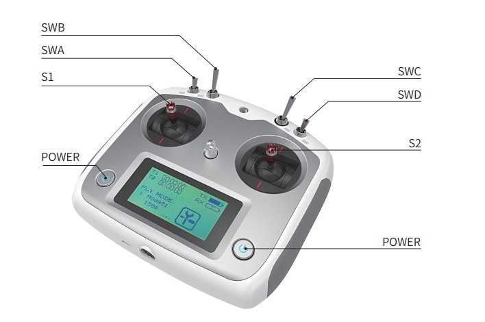
Getting Started:
- The remote control needs to be turned on before the four paddles of SWA, SWB, SWC, SWD to the forefront
- Ensure that the chassis two emergency stop switch are open, emergency stop switch pop-up state for the control mode, press to enter the safety mode
- POWER is the power button, press and hold both power buttons at the same time to turn on.
- Move SWB to the middle
- The S1 controls forward and backward movement,the S2 controls the robot forleft rotation and right rotation.
3.6 Light control instructions
Thunder front and rear are equipped with lights, in order to facilitate customers, THUNDER open the light control interface to the outside. At the same time, in order to save energy, the light control interface is reserved in the remote control. The version of remote control only supports FS remote control at present, and the adaptation of other remote controls is still in progress. At present, there are 3 lighting modes in the remote control, and the mode can be switched by SWC toggle:
Mode control description: SWC dial to the bottom for normally closed mode, the middle for normally open mode, the top for breathing light mode;
Normally closed mode: In normally closed mode, if the chassis is stationary, the headlights will be turned off, and the taillights will enter the breathing light mode in order to indicate the current working status: if the chassis is driving at normal speed, the taillights will be turned off and the headlights will be turned on;
- Normally open mode: In the normally open mode, if the chassis is stationary, the headlights are normally open, and the taillights will enter the breathing light mode in order to indicate the stationary state; if in the motion mode, the taillights are closed and the headlights are open;
- Breathing light mode: the headlights and taillights are in breathing light mode in various states.
3.7 Safety Information
3.7.1 Environment Considerations
- For the first use,please read this manual carefully to understand the basic operating content and operating specification.
- Use Thunder always under -20℃~45℃ ambient temperature.
- If Thunder is not configured with separate custom IPprotection, its water and dust protection will be IP22 ONLY.
- Make sure each device has sufficient power.
- Make sure Thunder does not have any obvious defects.
- Check if the remote controller battery has sufficient power.
3.7.2 Check
- Please charge in time when the device is low battery alarm.
- When Thunder has a defect, please immediately stop using it to avoid secondary damage.
- When device has had a defect, please contact the relevant technical to deal with it, do not handle the defect by yourself.
3.7.3 Operation
- When using, make sure the emergency stop switch has been released.
- Ensure that the area around is relatively spacious.
- Carry out remote control within the range of visibility.
- The maximum load capacity of Thunder is 80KG. When using, make sure the payload does not exceed 80KG.
- When installing an external extension on Thunder, confirm the position of the center of mass of the extension and make sure it is at the center of rotation.
3.7.4 Charging
- Thunder is equipped with a charger by default to meet customers' charging demand;
- We recommend that you turn the robot off before charging. And there is no indicator light provided on the site while charging. For specific indicator lights, please refer to the description on the charger.
- Make sure the Thunder chassis is in a shutdown and power-off state.
- Make sure Q4 (knob switch) in the tail electrical console is off before charging.
- When charging, make sure the ambient temperature is above 0℃;
- Plug the charger into the Q1 charging interface in the electrical control panel at the rear of the robot.
- Connect the charger to power supply and turn on the switch in the charger. Then, the robot enters the charging state;
- Note: The battery needs about 3 hours to be fully recharged from 22 V, and the voltage offully-recharged battery is about 29.2 V(The battery type here is ternary lithium battery, if the battery type is lithium iron phosphate, the maximum voltage will be 26.8V); the recharging duration is calculated as 30 AH ÷ 10A = 3h;
3.7.5 Maintenance
- According to the IP protection level of the device,please use Thunder in the environment with the protection level requires for the equipment.
- Do not push the robot directly.
- If the robot shakes in the process of rotation in place, adjust the suspension.
- Tire pressure is checked regularly, keep tire pressure at 1.8bar~2.0bar.
- Replace tires in a timely manner if they are badly worn or flat.
4 Performance parameters
| Parameter Type | Project | Indicator |
|---|---|---|
| Mechanical parameters | lengthxwidthxheight | 950x718x560 |
| wheelbase (mm) | 498 | |
| front/rear track(mm) | 582/582 | |
| body weight(Kg) | 88Kg | |
| Rated load | 80kg(customizable) | |
| Battery Type | lithium battery24V 30Ah | |
| motor | DC brushless 4 X 400W | |
| Gearbox | 1:40 | |
| drive form | four-wheel independent drive | |
| suspension | Double rocker independent suspension | |
| turn | Four-wheel differential steering | |
| safety equipment | Servo Brake / Crash Tube / Crash Bar | |
| Performance parameters | No-load maximum speed (m/s) | 1.5 |
| Minimum turning radius | Can turn in place | |
| Operating temperature | -10C°~+45C° | |
| Maximum gradeability | ≤25° | |
| Minimum ground clearance (mm) | 135 | |
| control parameter | control mode | Remote Control/Control Command Mode |
| remote control | 2.4G / limit distance 200m | |
| Communication Interface | CAN / RS232 |
5 The Main Components
5.1 Camera parameters
| Itemst | Values |
|---|---|
| depth range | 0.11m—10m |
| deep field of view | 85.2°(H) x 58°(V) |
| depth frame rate | 90FPS |
| Resolution | 1920x1080 |
| video frame rate | 30FPS |
5.2 Lidar
5.2.1 Performance parameters
| Project | Parameter |
|---|---|
| Measuring distance | 25m |
| Sampling frequency | 16KHz |
| scanning frequency | 10KHz |
| Angular resolution | 0.225° |
| Communication Interface | TTL UART |
| communication rate | 256000bps |
5.2.2 Communication Interface
| Color | Signal name | Type | Discription | Minimum | Typical value | Maxmum |
|---|---|---|---|---|---|---|
| red | VCC | power | total power supply | 4.9V | 5V | 5.5V |
| ellow | TX | out | Ranging core serial output | 0V | 3.3V | 3.5V |
| green | RX | in | Ranging core serial input | 0V | 3.3V | 3.5V |
| black | GND | power | ground wire | 0V | 0V | 0V |
| blue | MOTOCTL | in | Scan motor enable/PWM control | 0V | 3.3V | 5V |
5.3 Ultrasound
| Project | Parameters |
|---|---|
| Maximum range | Measure wall 8 meters, measure people 2 meters, measure water surface/robot about 4 meters |
| wave speed angle | 5-10 degrees within 30cm, 60-70 degrees above 30cm |
| Communication Interface | TTL serial port |
| output method | USB output |
5.4 Router
| Item | Parameters |
|---|---|
| Support network | 4G full Netcom |
| 4G rate | 150Mps |
| network port | Four Gigabit Ethernet ports |
| Antenna interface | 2 external antenna holes |
| wireless rate | 2.4G Mhz/5G Mhz |
| Dual network dual access | Support (4G + broadband overlay Internet access) |
6 Expanding board
On the robot, We also provide users with power extension interfaces for expanded pplications. The details are as follows:

| No. | Type | Voltage |
|---|---|---|
| A | MR30 | 5V / 12V |
| B | MR30 | 5V / 12V |
| C | XT30 | 5V |
| D | XT60 | 24V |
| E | MR30 | 5V / 12V |
| F | MR30 | 5V / 12V |
7 Q&A
Q:Thunder is started up correctly, but why cannot the RC transmitter control the robot body to move?
A:First, check whether the E-stop switches are released; then, check whether the controlmode selected with the top left mode selection switch on the RC transmitter is correct.
Q:Thunder gives "beep-beep-beep..." sound while running, how to deal with this problem?
A:If Thunder give this "beep-beep-beep" sound continuously, it means the battery is in the alarm voltage state. Please charge the battery in time.
Q:Is it normal for the Thunder to experience tire wear during operation?
A:Thunder in the process of running tire wear is a normal phenomenon. As Thunder adopts the design of four-wheel differential steering, sliding friction and rolling friction will occur in the process of robot rotation, and if the ground is not smooth and the surface is rough, there is wear on the tire surface at this time. In order to reduce the wear or slow down the process of wear, you can use the form of small angle turning to minimize the form of rotation in place.
Q:Why is the Thunder on but the screen remains black?
A: The shaking during transportation may cause the signal cable to become loose. We recommend that you try pluging the cable back in.